DIY Moffenzeef Dialup Clone on Stripboard
I really wanted some glitchy drums in my rack, and Ross Fish over at Moffenzeef Modular has made some really great ones. He also released all the code and schematics (although somewhat cryptic) on GitHub. His circuits are pretty straightforward and make for nice DIY projects.
What I really wanted was a Moffenzeef Muskrat, but I decided to do the Dialup first as a warmup. The two modules have nearly identical circuits; the Muskrat just has more CV inputs.
In this post, I’ll document how I cloned the Dialup.
Schematic
The schematic on Moffenzeef’s GitHub doesn’t have labels for all the components, so I needed to label them by hand if I wanted to create a properly labeled strip board layout. Consult the BOM in the Stripboard Layout for all the proper component values. Do not infer component values from this schematic. The component labels in this schematic match the stripboard layout.
And here is the original schematic from Moffenzeef’s GitHub (19.5 MB) for reference.
One important modification to note in my version is that I have swapped out the SP3T slide switch for an SPDT on-off-of toggle switch. This means that in the center position, only C1 is connected to the op amp IC1B. In the other two positions, either C2 or C3 is also connected, along with C1. Because capacitance is added in parallel, the three capacitance values are:
- C1
- C1 + C2
- C1 + C3
If you use C1=4.7uF, C2=4.7uF, and C3=33uF or C3=47uF, then you should come fairly close to the original three capacitor values (4.7uF, 10uF, and 47uF).
How the Dialup Works
Microcontroller
At the core of the Dialup is an ATTiny85 MCU. This chip is programmed to generate the glitchy audio, and has one analog input to control the pitch/glitch parameter. The audio comes out of PB1/MISO as a PWM signal.
VCA
The PWM signal goes through a single-transistor VCA (T2). The audio goes to the base of the transistor, and the output of the envelope follower (labeled “A/R envelope”) is sent to the collector to control how much audio passes through. I believe this is known as a “swing type VCA,” very famously used in devices like the TR-808.
Envelope follower
Diode D5 allows any rise in voltage coming out of U1A to instantly charge the capacitor (C2, C3, or C4). The time it takes for the capacitor to discharge is determined by the decay pot RV1, thanks to D3.
Stripboard layout
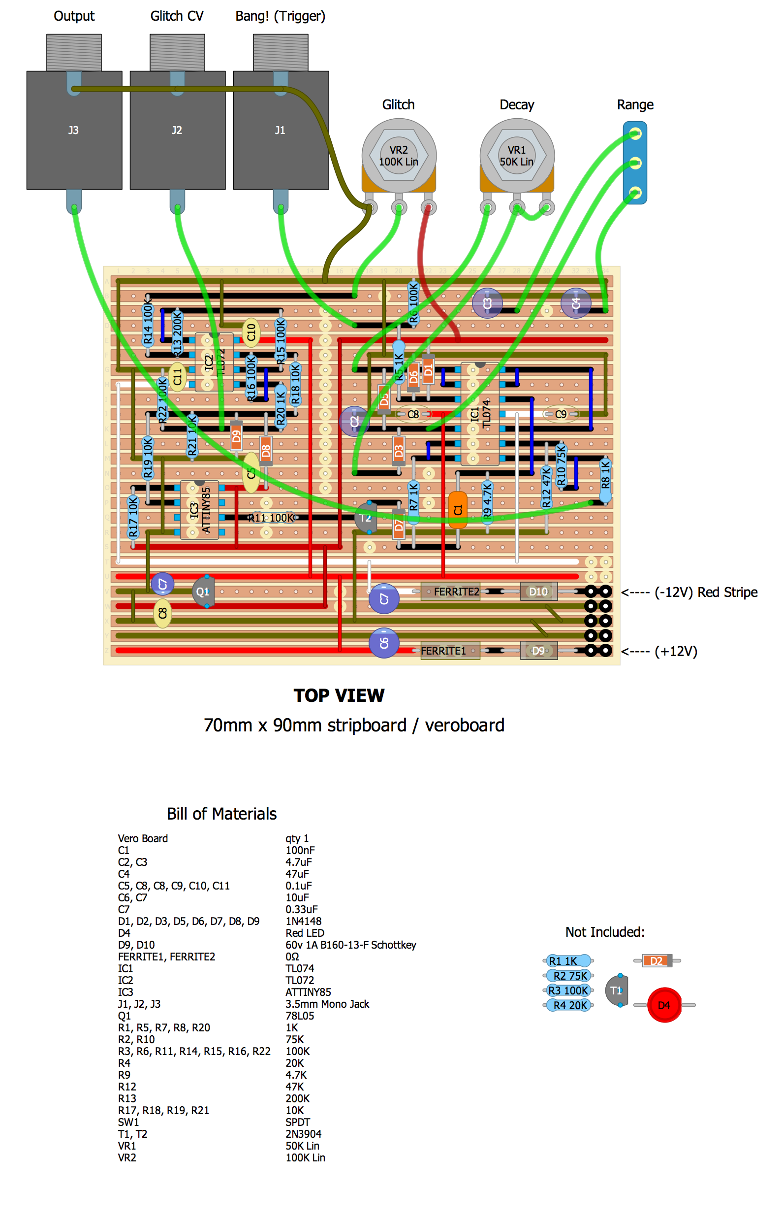
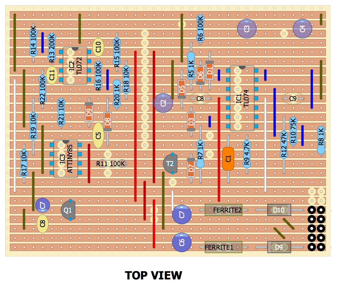
Here is the stripboard layout. It should work for you if you don’t goof up the soldering. I used this strip board available from Amazon. The part values in the BOM are the ones from the original schematic, not necessarily the ones I ended up using (see the Notes section for info on component replacements).
Full stripboard layout, including colored tracks, with BOM:
Stripbord cuts, bottom view:
Stripboard layout, components only, top view:
Programming the ATTiny85
I used an Arduino Uno as a programmer to download the Dialup firmware to the ATTiny. Here is a great tutorial on how to do this:
https://medium.com/jungletronics/attiny85-easy-flashing-through-arduino-b5f896c48189
NOTE: Don’t install the 10uF capacitor until AFTER you load the ArduinoISP sketch to the Arduino. The capacitor is there to ignore any “reset” pulses sent by the Arduino IDE. If you put the capacitor in before loading the ArduinoISP firmware, then the firmware will fail to be loaded to the Arduino.
Notes
- You MUST use a socket for the ATTiny.
- I couldn’t fit the LED driver onto the strip board, so you’ll need to find a place for that yourself if you want it. For fewer components, try the LED driver from Moffenzeef’s Muskrat module.
- DOUBLE CHECK THE 78L05 PINOUT BEFORE SOLDERING!
- Before plugging in power, check for shorts between the power rails.
- If you have an audio taper pot lying around for the Decay pot, you’ll probably want to use it. It would give you better control over the decay that a linear pot.
- Use either ferrite beads or 0 Ohm resistors for FERRITE1 and FERRITE2. 10 Ohm would also probably work.
- You may need to mess around with the resistance value for the Decay pot and the capacitor values for C2, C3, and C4 to get a variety of decay ranges that suit your tastes.
- I substituted the 50k Decay pot with a 100K and used C2=0.47uF, C3=1uF, and C4=10uF
- I didn’t have any 75k resistors, so I used a 68k for R10 and everything seems to work just fine.
- I replaced the power protection diodes D9 and D10 with 1N4001s and it works fine.
If you have any questions about substituting any other components, feel free to ask in the comments!
Gallery
Demo
Here’s a jam I did with the Dialup as the main foreground drum element:
That’s it!
Let me know what you think in the comments! Or ask any questions if you have them :)


